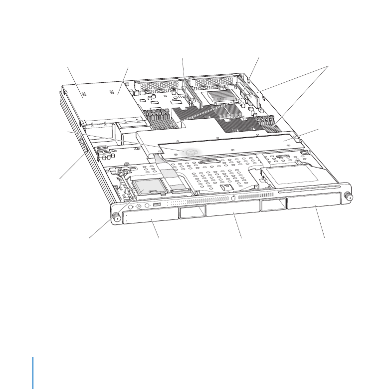
Xserve at a Glance—Internal Components
DIMM
slots
Fan array
Expansion slot 1
Power supply
bay 2
Power supply
bay 1
Expansion slot 2
Battery
Rack
release latch
SSD (optional)
Drive bay 1
Drive bay 2
Drive bay 3

23
Chapter 2
Installing or Replacing Components
Power supply bays
You can install one or two power supplies in the Xserve. When two supplies are installed,
they share the load. If one supply fails, the other takes over the full load. See “Installing or
Replacing a Power Supply” on page 28.
Expansion slots
You can install a half-length (6.6 inch) PCI-E card in slot 1 and a 9 inch PCI-E card in slot 2.
See “Installing a PCI Express Card” on page 38.
DIMM slots
You can install up to twelve error-correcting dual inline memory modules (DIMMs) in
these slots. See “Adding Memory” on page 33.
Fan array
The fan array draws cooling air through the Xserve from front to back.
Drive bays
You can install SATA (Serial ATA) Apple Drive Modules or qualified third-party SAS (Serial
Attached SCSI) drive modules. See “Installing or Replacing a Drive Module” on page 24.
Solid-state drive (SSD)
If you ordered your system with an SSD, the Xserve comes with the SSD set up as the
startup disk.
Rack release latch
This latch stops the Xserve about halfway out of the rack. Press to release.
Battery
The battery on the main logic board powers the system clock and preserves basic
system settings (in NVRAM) when power supplies are disconnected. See “Replacing the
Battery” on page 43.

24
Chapter 2
Installing or Replacing Components